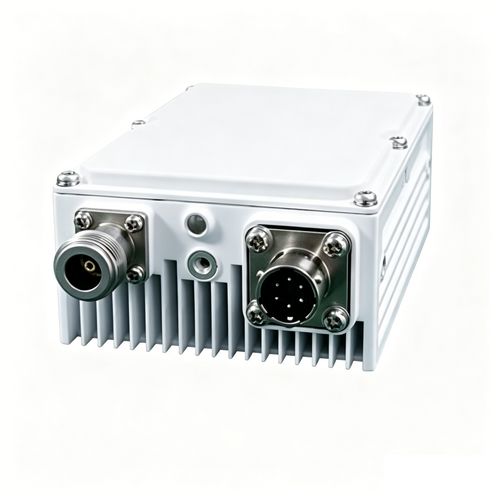

Q-BAND LNA
Technical Highlights
37.5–40GHz Q-Band Operation
The amplifier operates across the 37.5–40GHz Q-band frequency range and is designed for millimeter-wave receiver front ends, satellite ground terminals and other Q-band receiving systems.
50dB Small Signal Gain
A specified small-signal gain of 50dB provides substantial amplification for low-level Q-band signals before subsequent frequency-conversion or signal-processing stages.
2.7dB Maximum Noise Figure
The low-noise signal path specifies a maximum noise figure of 2.7dB, helping limit receiver-noise contribution while amplifying weak incoming Q-band signals.
Adjustable Gain Control
Gain can be adjusted over a 0–20dB range in 0.5dB steps, supporting receiver-level control and system balancing across different signal and downstream-equipment conditions.
Controlled Group Delay
Specified linear, parabolic and ripple group-delay performance supports wideband receiver applications in which signal timing and transmission characteristics must remain controlled.
Integrated RF Sampling Port
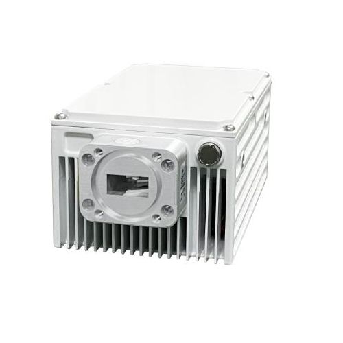
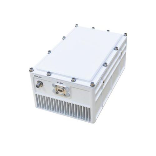
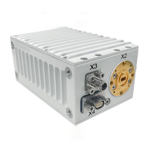
A separate 1.85mm-K RF sampling interface provides a dedicated connection for compatible measurement and monitoring equipment without replacing the main WR-22 signal interfaces.
Protected Connectorized Module
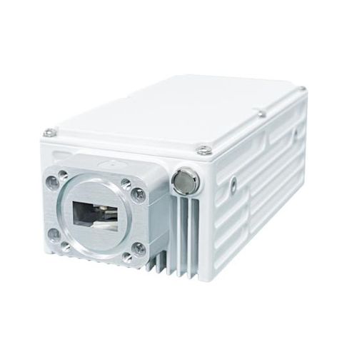
The IP65 enclosure, WR-22 waveguide interfaces and operating temperature range from -40°C to +60°C support integration into protected outdoor and industrial Q-band receiver installations.
RF Specifications
| Operating Frequency | 37.5–40GHz |
|---|---|
| Small Signal Gain | 50dB |
| Gain Adjustment | 0–20dB in 0.5dB steps |
| Gain Variation over 1000MHz | 2dB p-p |
| Gain Variation over Full Band | 3dB p-p |
| Noise Figure | 2.7dB maximum |
| In-Band Spurious Emission | ≤-50dBc |
| Out-of-Band Spurious Suppression | ≤-60dBc |
| RF Input VSWR | ≤1.5:1 |
| RF Output VSWR | ≤2.0:1 |
| Group Delay over 20MHz | Linear: ≤0.05ns/MHz Parabolic: ≤0.03ns/MHz² Ripple: ≤1.0ns p-p |
| Group Delay over 1GHz | Within f0 ±35% of single-channel bandwidth: ≤5ns Within f0 ±50% of single-channel bandwidth: ≤10ns |
| Channel Delay Stability | ≤0.01ns over 24 hours |
Interfaces
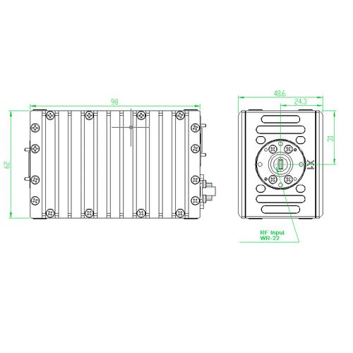
| RF Input | X1, WR-22 waveguide interface |
|---|---|
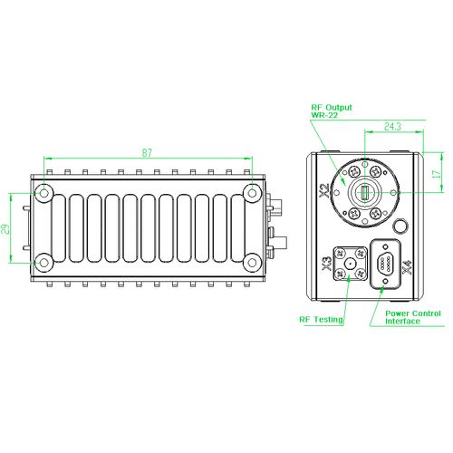
| RF Output | X2, WR-22 waveguide interface |
| RF Sampling Interface | X3, 1.85mm-K connector |
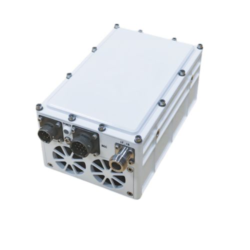
| DC and M&C Interface | X4, 9-pin connector |
| Status Indicator | Green: normal operation; red: fault |
Physical and Environmental Specifications
| Power Supply | 24V DC ±1V |
|---|---|
| Power Consumption | 10W |
| Outline Dimensions | 98 × 62 × 49mm (3.9 × 2.4 × 1.9in) |
| Weight | 0.5kg (1.1lb) |
| Operating Temperature | -40°C to +60°C (-40°F to +140°F) |
| Storage Temperature | -50°C to +70°C (-58°F to +158°F) |
| Ingress Protection | IP65 |
Recommended Applications
Q-band satellite receiver front ends
Satellite gateway and earth-station receive chains
Millimeter-wave communication receivers
Q-band antenna and feed-system integration
Research and laboratory measurement systems
OEM Q-band receiver subsystems
Integration Notes
Supply the module with regulated 24V DC within the specified ±1V tolerance.
Confirm the X4 9-pin power and monitoring connector pinout before applying power.
Align the WR-22 input and output waveguide flanges correctly to prevent excessive mismatch or damage.
Use the X3 1.85mm-K connector only as the specified RF sampling interface.
The attachment does not state the maximum safe RF input power. Confirm this value before final system integration.
Keep the enclosure cooling fins unobstructed and provide adequate airflow around the module.
Use suitable flange sealing and connector protection when installing the module in an outdoor environment.
Confirm the gain-control and monitoring commands before integrating the module with external control equipment.
FAQ
What is the 37.5–40GHz Q-Band LNA?
It is a Q-band low noise amplifier module designed to amplify low-level signals in a receiver front end while limiting the additional noise introduced into the receive chain.
What frequency range does the amplifier support?
The specified operating-frequency range is 37.5GHz to 40GHz.
What is the small-signal gain?
The amplifier provides a specified small-signal gain of 50dB.
Can the gain be adjusted?
Yes. The gain can be adjusted over a 0–20dB range in 0.5dB steps for receiver-level control and system balancing.
What is the maximum noise figure?
The specified maximum noise figure is 2.7dB.
What is the specified gain variation?
Gain variation is specified at 2dB peak-to-peak over 1000MHz and 3dB peak-to-peak across the full operating band.
Which RF interfaces are used?
The main RF input and output use WR-22 waveguide interfaces. A separate 1.85mm-K connector is provided for RF sampling.
What are the specified input and output VSWR values?
The RF input VSWR is specified at no more than 1.5:1. The RF output VSWR is specified at no more than 2.0:1.
What is the purpose of the RF sampling interface?
The X3 1.85mm-K interface provides an RF sampling connection for compatible monitoring and measurement equipment.
What power supply is required?
The amplifier requires a regulated 24V DC supply with a tolerance of ±1V. Its specified power consumption is 10W.
What does the status LED indicate?
A green indication represents normal operation, while a red indication represents a detected fault condition.
Can the LNA be installed outdoors?
The enclosure is rated IP65 and supports operation from -40°C to +60°C. Correct waveguide sealing, connector protection and thermal installation are still required.
What are the module dimensions and weight?
The outline dimensions are 98 × 62 × 49mm, and the specified weight is 0.5kg.
What should be checked before installation?
Confirm the supply voltage, 9-pin connector pinout, gain-control method, WR-22 flange alignment, RF sampling connection and environmental sealing before applying power.
B2B Procurement FAQ
What information should be included in a quotation request?
Include the required quantity, operating-frequency range, gain, noise figure, gain-control requirements, interface configuration, destination country and requested delivery schedule.
Does the supplied material identify a model number?
The supplied material identifies the product as a Q-Band LNA but does not provide an independent model or part number. Buyers should request a confirmed part number before ordering.
Can frequency or gain specifications be customized?
Any requested change to frequency range, gain, gain adjustment or interfaces must be reviewed and documented during quotation. Availability depends on the required technical configuration.
Can a sample unit be requested for evaluation?
Sample availability, price and delivery time must be confirmed during quotation. The intended receiver architecture and test conditions should be included in the request.
Which RF tests are recommended before shipment?
Recommended tests include operating frequency, small-signal gain, gain adjustment, gain flatness, noise figure, VSWR, spurious response, group delay and channel-delay stability.
Which functional inspections should be performed?
Inspections should cover DC power consumption, gain-control operation, RF sampling, monitoring communication, LED status and connector condition.
Which mechanical checks are recommended?
Check the enclosure dimensions, mounting points, cooling fins, WR-22 flange condition, RF sampling connector, 9-pin connector, sealing surfaces and product labeling.
Which documents should buyers request?
Request the latest specification sheet, mechanical drawing, connector pinout, gain-control protocol, inspection report, packing list and any required compliance documents.
Can packaging and product labeling be customized?
Labeling, serial-number format, documentation and packaging requirements can be submitted with the RFQ. Availability and minimum quantities must be confirmed before production.
How are lead time and warranty confirmed?
Lead time and warranty terms depend on the order quantity, technical configuration and production schedule. They must be stated in the final quotation or supply agreement.