

CYCLONE ELRS 2400RX-7CH V1.1 Receiver
Technical Highlights
2.4GHz ExpressLRS Receiver
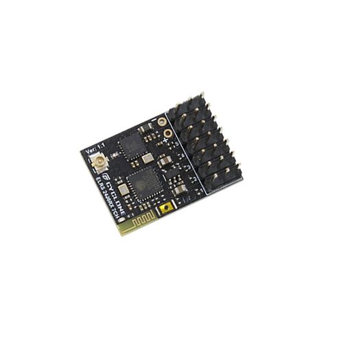
The CYCLONE ELRS 2400RX-7CH V1.1 is a 2.4GHz radio-control receiver designed for ExpressLRS-based RC and FPV control systems. It is a control receiver rather than an analog or digital video transmitter.
Seven Direct PWM Outputs
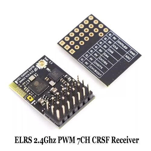
Seven independently labelled channel connections allow servos, an ESC or other compatible PWM-controlled equipment to be connected directly to the receiver. Each channel position is accompanied by 5V and ground connections.
PWM and CRSF Interface Support
The board supports direct PWM channel connections and identifies CH2 as TX and CH3 as RX for a CRSF serial connection. The required output configuration must be selected in the receiver firmware before connecting the target device.
External Copper-Tube Antenna
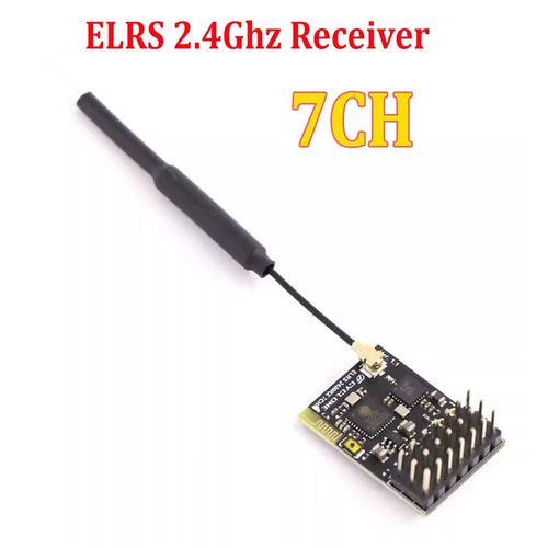
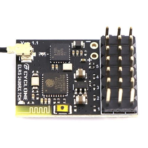
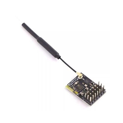
An external copper-tube antenna connects to the receiver through a detachable micro-coax connection. The external antenna arrangement allows the antenna to be positioned away from conductive frame components and onboard electronics.
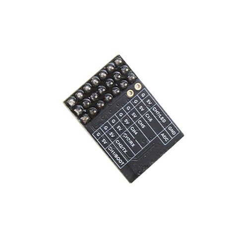
Clearly Labelled Connection Layout
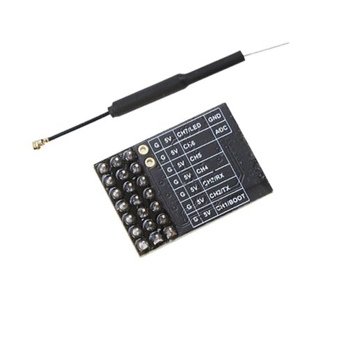
The reverse-side silkscreen identifies ground, 5V, CH1 through CH7, TX, RX, LED, BOOT, ADC and GND connections, supporting accurate wiring during installation and maintenance.
ExpressLRS 3.2 Support
The supplied product information identifies ExpressLRS 3.2 support. The receiver and transmitter module should use compatible major firmware versions and matching regulatory-domain settings.
Receiver Specifications
| Brand | CYCLONE |
|---|---|
| Board Model | ELRS 2400RX-7CH |
| PCB Version | Ver. 1.1 |
| Product Type | ExpressLRS PWM receiver |
| Operating Band | 2.4GHz |
| PWM Outputs | 7 channels |
| Serial Output | CRSF through the labelled TX and RX connections |
| Power Connection | 5V and ground headers |
| Antenna | External copper-tube antenna |
| Firmware Support | ExpressLRS 3.2 |
Connection Layout
| CH1 / BOOT | Channel 1 PWM connection with the board-labelled BOOT function. |
|---|---|
| CH2 / TX | Channel 2 PWM connection and labelled serial TX connection. |
| CH3 / RX | Channel 3 PWM connection and labelled serial RX connection. |
| CH4 | Channel 4 PWM output. |
| CH5 | Channel 5 PWM output. |
| CH6 | Channel 6 PWM output. |
| CH7 / LED | Channel 7 PWM connection with the board-labelled LED function. |
| ADC | Board-labelled ADC connection. The electrical limits and required scaling must be verified before use. |
| 5V / G | Five-volt and ground connections are arranged alongside the channel headers. |
Output Configuration
Use the labelled CH1–CH7 connections when direct PWM output is required.
Use the labelled TX and RX connections when the receiver is configured for CRSF serial communication.
Confirm the receiver output mapping before connecting servos, an ESC or a flight controller.
Functions sharing channel labels, including BOOT, TX, RX and LED, may depend on the selected firmware configuration.
Do not assume that PWM and CRSF functions are active simultaneously without checking the receiver configuration.
Installation Notes
Connect the receiver only to a regulated 5V supply through the correctly labelled power and ground pins.
Verify connector orientation and channel assignments before applying power.
Keep the antenna connected during operation and avoid repeatedly loading the micro-coax connector.
Position the exposed antenna section away from carbon-fibre parts, batteries, high-current wiring and other conductive materials.
Secure the receiver and antenna so that vibration or cable movement cannot pull on the antenna connector.
Confirm that the transmitter module and receiver use compatible ExpressLRS firmware and matching frequency-domain settings.
Perform binding, channel-direction, failsafe and control-range checks before operating the aircraft.
Recommended Applications
Fixed-wing aircraft requiring direct PWM servo outputs.
RC models using up to seven receiver channel connections.
FPV aircraft using an ExpressLRS 2.4GHz control link.
Flight-controller installations requiring a CRSF receiver connection.
FAQ
Is the CYCLONE ELRS 2400RX-7CH a video transmitter?
No. It is a 2.4GHz ExpressLRS radio-control receiver. It does not transmit FPV video and does not provide VTX frequency-channel or video-output-power settings.
How many PWM outputs does the receiver provide?
The board provides seven labelled PWM channel connections, identified as CH1 through CH7.
Does the receiver support CRSF output?
Yes. The board identifies CH2 as TX and CH3 as RX for a CRSF serial connection. The required serial-output mode must be selected in the receiver configuration.
What input voltage should be used?
The power headers are labelled 5V and ground. Use a regulated 5V supply and verify polarity before applying power.
Which ExpressLRS firmware does it support?
The supplied product information identifies ExpressLRS 3.2 support. Confirm firmware compatibility between the receiver and transmitter module before binding.
What type of antenna is supplied with the receiver?
The product images show an external copper-tube antenna connected through a detachable micro-coax connector.
Can the receiver be connected directly to servos?
The seven PWM channel headers include signal, 5V and ground positions for direct PWM device connections. Verify the connected device voltage, channel mapping and current requirements before installation.
B2B Procurement FAQ
Which product identification should be included in an inquiry?
Please identify the product as CYCLONE ELRS 2400RX-7CH Ver. 1.1 and specify the required quantity, destination market and intended PWM or CRSF installation.
Should this product be listed as a VTX or receiver?
Its technical product type is an ExpressLRS receiver. If it is placed in a VTX website category for commercial organization, the product title and specifications should still clearly identify it as a receiver.
What should be verified before a bulk order?
Confirm the exact PCB version, installed firmware version, antenna configuration, pin-header configuration, stock status, packaging, lead time and required compliance documentation during quotation.
Can PWM and CRSF requirements be included in the purchase specification?
Yes. The intended output mode and channel arrangement should be stated in the technical inquiry. Firmware configuration or preparation requirements must be confirmed during quotation.
Are product dimensions and weight available from the supplied material?
No reliable dimensions or weight are shown in the supplied images. Confirm the production-unit drawing and weight before completing mechanical integration or procurement documentation.
Leave Your Message
Products categories
-
GEPRC ELRS 915M/2.4G C3 Gemini Xrossband
-
SKYDROID 5.8G 150CH UVC OTG FPV Receiver
-
FS2A Mini 4CH AFHDS 2A PWM Receiver
-
TBS Crossfire Nano RX
-
1.2GHz 1500mW Wireless AV Transmitter an
-
Foxeer ELRS 915/868MHz Receiver
-
GEPRC ELRS Nano 915M PA500 Receiver
-
Flysky FGr4 / FGr4S / FGr4P AFHDS 3 Rece
-
CYCLONE ELRS 2400RX-7CH V1.1 Receiver
-
DAKEFPV Ultra1600 / Ultra2500 64CH Analo