

GY-GPSV3 NEO-M8N UART GPS Module
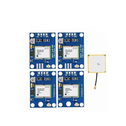
Technical Highlights
NEO-M8N Multi-GNSS Receiver
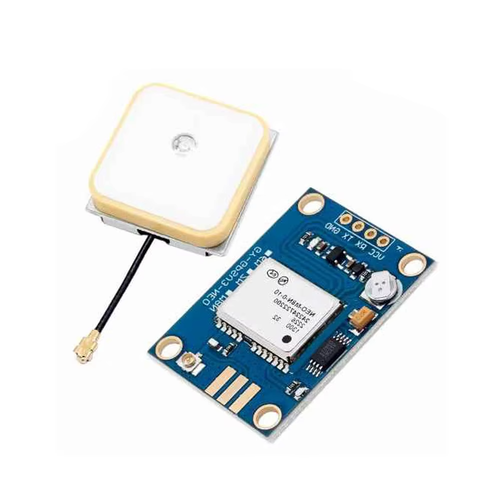
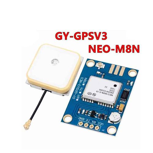
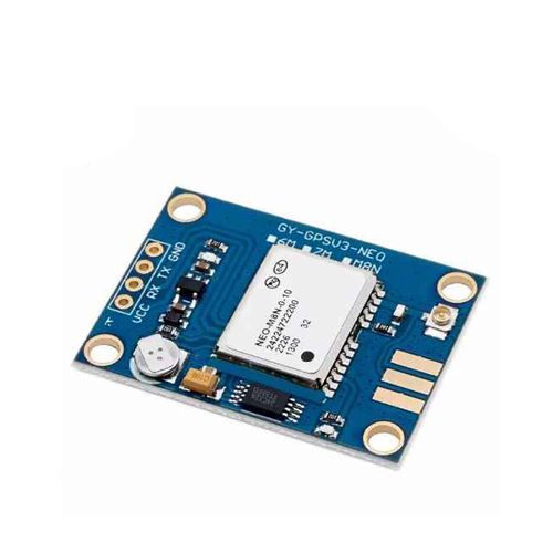
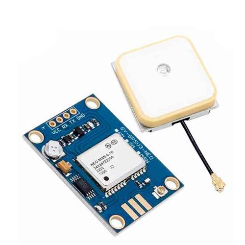
The GY-GPSV3 board is shown with a receiver marked NEO-M8N-0-10. On SPG 3.01 firmware, the receiver supports GPS, GLONASS, BeiDou and Galileo, with QZSS and SBAS support. The active constellation combination depends on the receiver configuration.
Four-Pad UART Connection
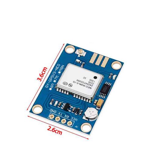
The carrier board exposes VCC, RX, TX and GND on one row of through-hole pads for integration with a suitable flight-controller UART.
Separate Patch Antenna
The pictured antenna is an external ceramic patch with a coaxial lead. Its separate mounting position allows antenna placement to be planned independently of the 36 × 26 mm PCB.
Receiver Performance
| Receiver Platform | u-blox M8, NEO-M8N |
|---|---|
| Maximum Navigation Update Rate | 5 Hz in GPS + GLONASS mode. 10 Hz in single-constellation mode. |
| Horizontal Position Accuracy | 2.5 m CEP in GPS-only or GPS + GLONASS mode. The receiver specification uses a 50% circular error measure over 24 hours of static testing at −130 dBm with more than six satellites. |
Board and Antenna
| Board Model | GY-GPSV3-NEO carrier board, NEO-M8N version |
|---|---|
| PCB Dimensions | 36 × 26 mm |
| Mounting | Four corner mounting holes |
| Pad Order as Marked | VCC, RX, TX, GND |
| Antenna Connection | Board-mounted coaxial socket for an external patch antenna |
Flight-Controller Integration
Use the carrier-board VCC rating and UART logic levels confirmed for the supplied revision. The NEO-M8N receiver itself has a VCC rating of 2.7–3.6 V DC.
Connect GPS TX to flight-controller RX and GPS RX to flight-controller TX. Connect the grounds together.
Match the flight-controller GPS protocol and serial baud rate to the receiver configuration.
Check the supplied antenna connector and route its coaxial lead without placing strain on the board socket.
FAQ
Which voltage should be used at the board VCC pad?
Use the VCC rating confirmed for the supplied carrier-board revision. The 2.7–3.6 V DC specification applies to the NEO-M8N receiver's own supply pin.
When does the NEO-M8N reach a 10 Hz navigation update rate?
The receiver is specified for up to 10 Hz in single-constellation mode. In GPS + GLONASS mode the specified maximum is 5 Hz. The configured rate depends on the firmware settings.
How should I check whether the board will work with my flight controller?
Identify the flight controller's UART pins, supply output and logic levels. Match these to the supplied carrier board and confirm that the flight-controller firmware supports the receiver's configured GPS protocol and baud rate.
B2B Procurement FAQ
What information should be included in a quotation request?
Specify the GY-GPSV3 NEO-M8N version, the required quantity and any requirements for the receiver firmware, carrier-board revision or antenna arrangement.
Which electrical details should be confirmed for a production order?
Request the carrier-board VCC range, UART input and output logic levels, and pad layout for the revision that will ship. State any electrical requirements that must match an existing harness or flight controller.
How can I confirm what comes with the board?
Ask the quotation to list the board, antenna, pin header and cables separately so the supplied items and quantities are clear. Availability, minimum order quantity and lead time are confirmed during quotation.
Leave Your Message
Products categories
-
HAKRC M10 GPS Module with QMC5883 Compas
-
GY-GPSV3 NEO-M8N UART GPS Module
-
GEPRC GEP-M1025 Series GPS Modules
-
GEPRC GEP-M10-DQ GPS Module with Compass
-
GEPRC GEP-M10 Series GPS Module (GEP-M10
-
Foxeer M10Q-250 GPS 5883 Compass Module
-
FlyFishRC M10 Mini GPS Module
-
FLY WING H1 6CH GPS Helicopter Flight Co
-
BZGNSS P15 Pro / P18 Pro / P25 Pro FPV G
-
Bainianxing BU-1025TF U-blox M10 GNSS GP