

3.3GHz 5W 64CH Analog FPV Video Transmitter
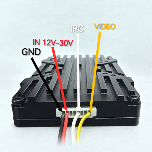
Technical Highlights
Eight Channel Groups
The channel table lists eight groups with eight positions per group. Listed center frequencies run from 3060 to 3500 MHz. Some frequencies appear in more than one group, so 64CH refers to selectable positions rather than 64 distinct frequencies.
Selectable RF Power Settings
The manual lists PIT, 25 mW, 1 W, 3 W, 4 W and 5 W settings. The 5 W value is the highest selectable setting; the manual does not state continuous-output test conditions or power tolerance.
IRC and Button Control
An IRC-labeled connection is provided, and the manual states that frequencies can be configured through Betaflight. Onboard buttons select power, channel position and channel group, with LED flash indications.
Finned Housing and Fan
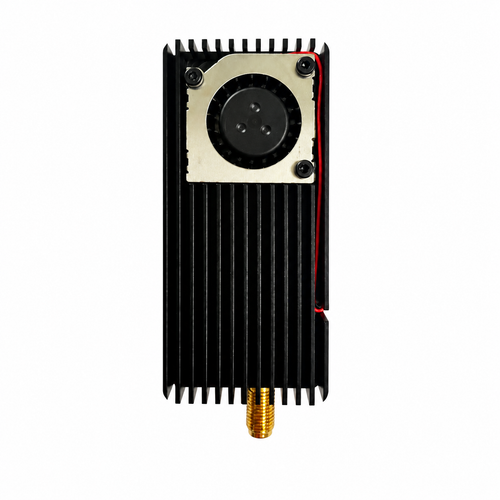
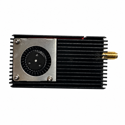
The illustrated housing has cooling fins and a fan. The manual requires installation clearance and airflow; overheating may reduce transmit power or shut down RF output.
Channel Frequencies
| Group | CH1 / CH2 / CH3 / CH4 / CH5 / CH6 / CH7 / CH8 (MHz) |
|---|---|
| FR1 | 3360 / 3380 / 3400 / 3420 / 3440 / 3460 / 3480 / 3500 |
| FR2 | 3200 / 3220 / 3240 / 3260 / 3280 / 3300 / 3320 / 3340 |
| FR3 | 3330 / 3350 / 3370 / 3390 / 3410 / 3430 / 3450 / 3470 |
| FR4 | 3170 / 3190 / 3210 / 3230 / 3250 / 3270 / 3290 / 3310 |
| FR5 | 3320 / 3345 / 3370 / 3395 / 3420 / 3445 / 3470 / 3495 |
| FR6 | 3310 / 3330 / 3355 / 3380 / 3405 / 3430 / 3455 / 3480 |
| FR7 | 3220 / 3240 / 3260 / 3280 / 3300 / 3320 / 3340 / 3360 |
| FR8 | 3060 / 3080 / 3100 / 3120 / 3140 / 3160 / 3180 / 3200 |
Electrical and Mechanical Specifications
| Video input | PAL / NTSC analog camera video |
|---|---|
| Power settings | PIT / 25 mW / 1 W / 3 W / 4 W / 5 W |
| Input voltage | 12–30 V DC |
| RF connector | Detachable SMA antenna connection |
| Cable interface | 8-pin, 1.0 mm |
| Pin assignment | 1 GND; 2 12–30 V; 3 12–30 V; 4 GND; 5 IRC; 6 5V-OUT; 7 TX-EN; 8 VIDEO |
| Mounting hole pattern | 20 × 20 mm / 25 × 25 mm |
| Dimensions | 68 × 32 × 16 mm; stated length excludes the antenna connector |
Installation Notes
Verify the 12–30 V supply, connector pinout and polarity before applying power.
Attach a suitable antenna to the SMA RF output before powering the transmitter.
Leave space around the housing and maintain airflow for cooling, particularly at higher power settings.
Match the selected center frequency with an analog video receiver that supports that exact frequency.
The manual identifies a 5V-OUT pin but gives no current rating for it; confirm the intended load before use.
FAQ
Does 64CH mean 64 different frequencies?
No. The manual lists 64 selectable positions across eight channel groups, but some center frequencies are repeated between groups.
What is the documented frequency span?
The channel table lists center frequencies from 3060 to 3500 MHz. The receiver must support the exact frequency selected on the transmitter.
Is 5 W a guaranteed continuous output rating?
5 W is the highest selectable setting listed in the manual. Continuous-output conditions, measurement tolerance and thermal derating data are not provided.
What power supply does the VTX require?
The documented input range is 12–30 V DC. Verify the connector pin assignment and polarity before applying power.
What control interface is specified?
The manual labels the control connection IRC and states that frequency can be configured through Betaflight. It does not identify a more specific IRC variant.
B2B Procurement FAQ
Can the exact brand and model number be confirmed?
The supplied manual does not identify either one. Confirm the product label and production revision during quotation.
Can measured power data be provided for the requested revision?
Request the RF test conditions, measured output at each power setting and thermal operating conditions during quotation.
What are the included accessories, MOQ and lead time?
The manual does not establish a packing list, MOQ or lead time. Confirm these details for the required quantity and configuration during quotation.
Leave Your Message
Products categories
-
3.3GHz 5W 64CH Analog FPV Video Transmit
-
1080–1380MHz 5W 16CH Analog FPV Video Tr
-
SKYZONE TX2501 CNC 56CH 2.5W FPV Video T
-
SKYDROID R12 2.4GHz 12-Channel Receiver
-
SKYDROID 5.8GHz 150CH Dual-Antenna UVC O
-
SKYDROID GR01 2.4/5.8GHz Dual-Band UAV R
-
SKYDROID 5.8GHz 150CH Dual-Antenna UVC O
-
RX5808 5.8GHz Dual-Antenna Diversity Vid
-
RUSHFPV TANK RACE II VTX
-
RUSHFPV X6172R 6.1G-7.2G XSPAN VRX Recei